
![]()

Stirling engine
Ce site appartient au réseau de sites relatifs aux moteurs à air chaud ou moteurs à apport de chaleur externe
![]()
Ce site appartient au réseau de sites relatifs aux moteurs à air chaud ou moteurs à apport de chaleur externe
Home page
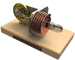
In its simplest description, a Stirling engine consists of a cylinder containing a gas and a piston
recovering the mechanical energy. This page proposes to discover the operation principles of this engine.
This is a gradual process by studying the following steps:
- the four basic phases
- The displacer function
- The Pressure-Volume diagram and the cycle efficiency
First observation : the gas used is confined, it's always the same. Another feature : energy is supplied
from outside of the cylinder, from where the designations "hot air engine" or
"external combustion engine" which one can read sometimes.
The thermodynamic cycle of the Stirling engine is very simple : it includes 4 phases during which the gas undergoes the following transformations :
The burner (the hot source) provides thermal energy. We easily imagine that the pressure and the gas temperature increase during this phase.

The volume increases whereas the pressure decreases. It is during this transformation that driving energy is produced.
The projected water (the cold source) recovers thermal energy. The temperature and the pressure decrease during this phase.
The pressure of gas increases whereas its volume decreases. One must provide mechanical energy to gas for this period.
One can see below the sequence of these various phases.


The realization of an engine such as the one described above would be difficult : kindle the burner,
extinguish it, sprinkle, then stop cooling, with many successive thermal shocks...
This is why one will introduce an artifice providing solutions to these problems: the displacer. This last
modifies neither the pressure nor the volume of gas, but requires it to be near the hot source located at
the top, or near the cold source located at the bottom.
Explanations through drawings :
The volume remains constant, but the displacer, while going down, sends the gas from the lower part (cold) to the top (hot).
The displacer follows the engine piston during the expansion so that the gas remains in contact only with the hot source.
The volume remains constant, but the displacer, while going up, sends the gas from the higher part (hot) to the lower part (cold).
The displacer, during compression, remains at the top so that the gas is always in contact only with the cold source.
The complete cycle is shown below. This engine is called the beta engine, its operation is studied more thoroughly on this site.

On the diagram above, one can see :
- The variation of hot volume, on the upper part, during the cycle (red zone).
- The variation of cold volume, at the bottom, between displacer and operating piston, during the cycle
(blue zone).
The principle of operation, above exposed, can be represented on a diagram called "Pressure-Volume diagram" or PV diagram.
On this diagram, one easily sees the four phases detailed above, by not
forgetting that expansion and compression are at constant temperatures (TM and Tm).
NB : the temperatures T are expressed in Kelvin (add 273 to the Celsius temperatures)
The coloured surface, ranging between the four segments describing the cycle, is representative of the
work collected during a cycle.
The demonstration is provided below.
At every moment, the force which is exerted on the piston is F = S x P where S is the surface of
the piston and P the instantaneous pressure.
The elementary work provided during a short time "dt" is equal to the instantaneous force multiplied
by displacement "dy" of the piston during this period "dt".
dW = F x dy
or
dW = S x P x dy
or, if it is noticed that S x dy = dV , the variation in volume during the period of time "dt"
dW = P x dV
On the PV diagram, this last expression is the elementary surface located under each curve. See opposite.
The work is positive under the curve of expansion because dV>0. Work is negative under the curve of
compression because dV<0.
The resulting work during a cycle is represented by surface under the curve of expansion decreased
by surface under the curve of compression. Therefore, it is the surface between the curves.
 The efficiency of the engine is equal to the ratio between the recovered
mechanical energy Wnet and the heat Qtotal that is required to provide. The latter
is provided during the isochoric heating and during the isothermal expansion.
The efficiency of the engine is equal to the ratio between the recovered
mechanical energy Wnet and the heat Qtotal that is required to provide. The latter
is provided during the isochoric heating and during the isothermal expansion.
With the opposite diagram, we can write :
Wnet = Wexp + Wcomp
Where, see above, Wcomp will be negative after its calculation.
Qtotal = Qheat + Qexp
The work, Wnet , is equal to sum of the recovered work (positive) during the expansion and the
provided work (negative) during the compression :
Wnet = Wexp + Wcomp
Wnet = ∫exp PdV + ∫comp PdV
with P = nRT / V
we obtain :
Wnet = ∫exp (nRTmax / V) dV + ∫comp (nRTmin / V) dV
Wnet = nR (Tmax - Tmin) ln Vmax / Vmin
During the isothermal expansion, the provided heat is equal to the recovered work during this same
phase :
Qexp = ∫exp PdV
Qexp = nR Tmax ln Vmax / Vmin
During isochoric heating, we have to provide :
Qheat = nCv (Tmax - Tmin)
where Cv is the constant-volume molar heat capacity of the gas when we heat it from
Tmin to Tmax.
The total provided heat is :
Qtotal = nCv (Tmax - Tmin) + nR Tmax ln
Vmax / Vmin
Now, we can write Stirling cycle efficiency :
Stirling cycle efficiency :
η = [R (Tmax - Tmin) ln Vmax / Vmin]
/ [Cv (Tmax - Tmin) + R Tmax ln Vmax / Vmin]
This efficiency is not equal to the Carnot cycle efficiency ! Even if, sometimes, we can read this
false affirmation.
ηCarnot = 1 - Tmin
/ Tmax
To obtain this equality, we have to suppose that the energy useful for isochoric heating is entirely
recovered during isochoric cooling, it is the function of the regenerator studied in the
"Regenerator" page. In this case, Cv (Tmax - Tmin
) disappears and we obtain :
η = [R (Tmax - Tmin) ln Vmax / Vmin]
/ R Tmax ln Vmax / Vmin
or, after simplification :
η = (Tmax - Tmin) / Tmax
or :
Stirling engine efficiency when there is a regenerator:
η = 1 - Tmin / Tmax
In reality, the regenerator efficacity is not equal to 100%. The Stirling engine efficiency will be always inferior to the Carnot cycle efficiency. And I am sorry for you...
Conclusion: we can say that the genius of Robert Stirling is not only in having imagined Stirling cycle , but rather in the invention of the regenerator (or economiser) which improves significantly the performance of engines !
This site was created and is maintained by Pierre Gras.
Thank you with all the people who contributed their shares: articles, photographs, videos, worksheets.
The author is opened with any suggestion allowing to improve this site for happiness of everybody. Finally, a big
thank you to Robert Stirling !
"stirlinengine.fr" site by Pierre Gras is licensed under a
Creative Commons License
 .
.
This site meets XHTML and CSS standards. To get the best, use a browser such as Firefox, Chrome, Safari, Opera... they also adhere to these standards.
