
![]()

Stirling engine
Ce site appartient au réseau de sites relatifs aux moteurs à air chaud ou moteurs à apport de chaleur externe
![]()
Ce site appartient au réseau de sites relatifs aux moteurs à air chaud ou moteurs à apport de chaleur externe
Home page
Jean-Pierre Van Dormael had the kindness to make a very interesting article on this subject. It is essential to understand this process of heat transfer to design correctly a Stirling engine, to choose the good gas, to ensure our own security.
It is not question of making long talks about the principles of Carnot or other developments relating to thermodynamics. However, in this chapter some bases are given which are quite useful to understand how a Stirling engine runs, what are the performances that one can expect.
When one wants to study a Stirling engine, it is necessary to have good bases of thermodynamics but also good bases of kinematics. Indeed, the kinematics will enable us to quantify, at any moment, volumes in the different parts of the engine.
When one associates the principles of thermodynamics and the elements of kinematics, one can easily (?) calculate the engine of our own design.
We know that the sound travels in the air at about 340 m / sec. For a Stirling engine, this high speed allows to admit that, if we ignore the pressure loss in exchangers, the pressure is the same throughout the engine, at any time. This assumption is often made in the methods of calculating Stirling engine.
The velocity of propagation heat in the air is much less known because the involved mechanisms are much more complicated. Let us try to see there a little more clearly.
The equation describing the propagation of heat in a substance can be deduced from three simple and almost obvious experimental observations.
The first observation is that in any point of a substance, the heat flows from hot to cold. The quantity of heat flowing per second (ie. its current) is proportional to two things: the thermal conductivity of the substance and the slope with which the temperature decreases at the observed point.
The second experimental observation is that the temperature of a volume containing a substance increases when a quantity of heat penetrates there. This increase in temperature is, of course, proportional to the quantity of heat received and inversely proportional to the volume, to the density of the substance which is there, and to its specific heat.
The third experimental observation is that no energy is created from nothing. The result is a principle of continuity: the heat which penetrates in an element of volume (according to the first observation) must necessarily correspond to that which makes increase its temperature (according to the second observation). In other words, in the absence of a source of heat in the volume, two afore-said heat quantities must be equal otherwise there would be creation of spontaneous heat, which is not possible.
To express mathematically these physical realities, we will be satisfied with only one dimension of space. That is enough to describe what occurs in a wire or a long and fine tube filled with gas. One will indicate by T(x,t) that the temperature T is a function of the position x in the tube and of the time t of the observation.
We will make the hypothesis that the thermal conductivity and the specific heat of materials are constant. It is not the case, but it is not very important for us: what interests us is to understand the physical mechanisms.
One can express the first observation above as follows:
δ Q = - k.S.(δ T(x,t)/δ x).δ t (1)
i.e. that the quantity of heat δ Q (joule) flowing for a short time δ t (en sec) through an area S (in square metres), is proportional to the temperature drop δ T (Kelvin degrees) found at the location x, at time t for a short distance δ x (en m) taken in the direction of flow. The ratio δ T(x,t)/δ x is not other than the partial derivative of T with respect to the variable x, i.e. its slope. The proportionality factor K is the thermal conductivity of the substance (i.e. its ability to conduct heat) and the minus sign indicates that the flow is in line with the temperature drop.
If one considers a small volume of tube or wire, section S and thickness Δ x, the net quantity of heat which penetrates is equal to the one which enters at the point x, less the one which leaves at (x + Δ x). One can write by taking account of the signs:
δ Q = k.S.{δ T(x+ Δ x,t)/δ x - δ T(x,t)/δ x}.δ t (1bis)
The second experimental observation can be written in the following way:
δ Q = ρ .c.δ T.S.Δ x (2)
i.e. that the quantity of heat δ Q (joule) which penetrated in small volume S.Δ x (m3), caused an temperature increase δ T (K). The coefficients of proportionality ρ (the Greek letter rho) and c are respectively the density of the substance (kg/m3) and its specific heat (J/kg/K). The latter expresses the quantity of heat which it is necessary to raise of one degree the temperature of one kg of the substance. For the gases which are compressible, this quantity is different according to whether the operation is done with constant volume or constant pressure. Below, we used the values corresponding to constant volume.
Lastly, the third physical fact, that of continuity, is written by equalizing the terms δ Q of the equations (1bis) and (2).
ρ .c.δ T.S.Δ x = k.S.{δ T(x+Δ x,t)/δ x - δ T(x,t)/δ x}.δ t (3)
By rearranging this equation by dividing it by δ t, by (ρ .c), by S and by Δ x, we obtain:
δ T/δ t = (k/(ρ .c)).{δ T(x+Δ x,t)/δ x - δ T(x,t)/δ x}/Δ x (3bis)
This equation says that the temperature variation δ T (degrees) during the short period of time δ t (seconds) i.e. the speed with which the temperature varies is proportional to the variation of the slope of the temperature (δ T/δ x) on the distance Δ x. The coefficient of proportionality is k/ρ .c. If Δ x approach zero, the expression{δ T(x+Δ x,t) /δ x - δ T(x,t)/δ x}/Δ x becomes the second partial derivative of T compared to x which is written δ 2T/δ x2. Finally, the equation (3bis) becomes:
δ T/δ t = (k/(ρ .c)).(δ ²T/δ x²) (3ter)
which is the partial differential equation of heat..
With this equation, it is possible to calculate the temperature profile, according to time, in a tube filled with gas and finished at both ends with a hot source and a cold source. Its resolution is not obvious. We use the famous harmonic series of Fourier. Above, you can see the result with a hot source at 800 degrees K on the left of the tube (x = 0). Initially all the gas is 300 degrees K.
The equation (3ter) indicates that the speed δT/δ t with which the temperature varies in a point, is proportional to the constant k/(ρ .c) of the gas used. And it is there that hydrogen and helium show a superiority compared to the air or nitrogen. In what follows, k is expressed in watt/meter/degree K, ρ in kg/m3 and c in joule/kg/degree K.
For air : k/(ρ .c) = 0,025 / (1,29 x 718) = 0,000027 m2/sec).
For helium : k/(ρ .c) = 0,14 / (0,164 x 3116) = 0,00027 m2/sec (10 times more than air).
For hydrogen : k/(ρ .c) = 0,18 / (0,083 x 10183) = 0,00021 m2/sec (8 times more than air).
For nitogen : k/(ρ .c) = 0,026 / (1,15 x 743) = 0,00003 m2/sec (almost like air).
Comparison with a metal:
For copper: k/(ρ .c) = 401/(8900 x 386) = 0,00012 m2/sec (4,4 times more than air).
For steel: k/(ρ .c) = 80,2/(7840 x 450) = 0,0000227 m2/sec (a little less than the air).
More quickly the heat diffuses in the gas, more easily we will be able to make run the engine with a high speed and with a great power. When we solve numerically the equation (3ter) (see the graph), we are surprised to note that the speed of diffusion falls quickly less than 3 mm/sec! This is more than 100,000 times slower than the speed of sound or pressure. This is really not fast. That shows that, in a Stirling engine, the totality of gas to be heated or cooled must be in very intimate contact with the exchangers. When we design a Stirling engine, to get a good efficiency it is necessary to take account this point.
If the engine does not run too quickly and if the exchangers are effective, it is not necessary to use hydrogen or helium. In this case, the only way to increase the power of an engine without changing its configuration or its initial velocity, is to increase the internal pressure of gas. A warning statement is essential here for those which would like to test this technique on a model. The use of air at high pressure into a Stirling engine can cause an explosion of vapors of the lubricating oil by diesel effect and the destruction of the engine. Such an explosion had caused the death of seasoned experimenters, for example in Philips Company. Choose low pressure when you use air, or an inert gas such as nitrogen or helium if you want to use high pressures.
Finally, we must still remember that the speed of propagation of heat in the gas is not the only factor for the efficiency and speed of a Stirling engine. There is also the transfer of heat between the exchangers and the gas. The speed of this transfer is roughly proportional to the difference in temperature and to the surface of the heat exchanger. The theory is highly complex, but in practice we see that the heat exchange is inversely proportional to the density of gas. We can still see that hydrogen and helium have a clear advantage over air or nitrogen.

To understand the operating principle of the Stirling engine, it is not necessary to know many things. It is considered that the gas used (air, hydrogen, helium, nitrogen...) is a perfect gas, i.e. that it obeys the following law: for a mass of gas given and at constant temperature, the product of the pressure of gas by its volume remains constant. It is Mariotte's law, we can write it like that:
PV = constant
where P represents the pressure of gas and V its volume.
If the temperature of gas is introduced, this law becomes:
PV = nRT
Where P represents the pressure of gas, V its volume, n the number of gram molecule (or the quantity of gas)), R the universal gas constant (R = 8,314 472 J / K mol) et T the temperature of the gas (expressed in Kelvin: T = t + 273, if t is the temperature expressed in Celsius degrees).
According to the good old principle: "nothing is lost, nothing is created, everything is transformed" we can approach the energy exchanges during a cycle of Stirling: any loss of calorific energy during a cycle is equal to the recovered mechanical energy during this same cycle.
On the diagram opposite, we see that we provide in calorific energy: Qexp + Qheat
However, we recover: Qcool + Qcomp
About the mechanical energy, we recover Wexp but we provide Wcomp
The overall balance becomes, by stipulating that the heat energy lost was fully transformed into mechanical
energy:
Qexp + Qheat - Qcool - Qcomp = Wexp - Wcomp
This leads us to speak about mechanical efficiency: it is the ratio of recovered mechanical energy (the engine goal, in fact) to the heat energy that we must provide:
Efficiency = ( Wexp - Wcomp ) / (Qexp + Qheat )
NB : as we can see it in the page the regenerator, it is not necessary to provide Qheat if a regenerator is installed. Indeed, at this time there, we recover Qcool
If we refer to the page the principles, we are able to show that the efficiency may be expressed according to the temperatures (expressed in Kelvin) of the heat source and of the cold source, according to the following formula:
Efficiency = 1 - Tm / TM
We assume, first, that the movement of moving parts of the engine are the consequence of the uniform rotation (ω = constant) of a motor shaft from 0° to 360° at each cycle. On the diagram opposite, you can see the representation of a slider-crank mechanism.
By supposing λ small, when the covered angle is φ , the value of d is:
d = r (1-cosφ) + 0,5λ r sin2 φ
where λ = r/L
When we know the section of the piston S, it is easy to determine the volume of gas V above the piston at each moment, for a given φ.
V = d S
When we have several pistons (alpha engine) or a piston and a displacer (beta and gamma engines), it is advisable to take into account the phase shift dφ between the two. The above equation becomes, for the second element:
d2 = r2 [1-cos(φ-dφ)] + 0,5λ2r2 sin2(φ-dφ)
where λ2 = r2/L2
In the same way that above, we obtain the value of instantaneous volume:
V2 = d2 S2
In this chapter, to calculate your engine, three types of approach are proposed to you:
- the first consists in applying the concepts studied above (kinematic and thermodynamic) by particularizing
them to the studied engines: alpha, beta or gamma.
- the second approach, the more pleasant, is to use the excellent worksheet of Jean-Pierre Van Dormael.
- finally, the third approach, suggested by Serge Klutchenko, is finer and does not take into account the
kinetics of the engine. The associated computation software is in course of completion and of checking.
Patience...
If you combine your knowledge in thermodynamics and those in kinematics, you can calculate your engine. By setting the maximum and minimum temperatures, the pressure in the engine can be calculated for each value of rotation of the main shaft.
There are several volumes to consider:
- a volume of expansion (variable).
- a volume of cooling (constant).
- a volume of regeneration of heat (constant).
- a volume of reheating (constant).
- a volume of compression (variable).
This is true whatever the type of engine, even if the diagram opposite seems show, rightly, an alpha
engine.
According to the engines, the expression of volumes of compression and expansion are not the same.
These volumes depend on the input variable, which is the angle of rotation φ.
In the table below, for three types of engine, we have collected the expressions of the volumes of expansion and of the volumes of compression:
Then, for each volume, it is necessary to apply the following relationship that adds the various gas masses (n is the number of gram molecules in the engine)
n = Σ PVi / RTi
In this expression, i takes the following values:
- i = e for the volume of expansion, Ti = TM
- i = cool for the volume of cooling, Ti = Tm
- i = reg for the volume of the regenerator, Ti = 1/2 ( Tm + TM )
- i = heat for the volume of reheating, Ti = TM
- i = c for the volume of compression,, Ti = Tm
It should be noted that we consider that the pressure is uniform throughout the engine at any moment.
Then, it is necessary to use a calculator or to use the worksheet made by Jean-Pierre Van Dormael, see below.
Stéphane Bastian has produced quite remarkable spreadsheets. They will help you design the engine with the characteristics you have chosen.
You will first choose the most appropriate ratio between displacer volume and motor volume, then you will obtain the PV diagram of your motor and a calculation of the power you can expect from it.
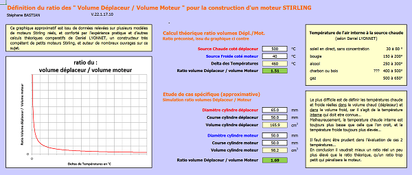
The purpose of this configurable spreadsheet is to provide an approximate determination of the volumes needed to build a Stirling engine, between the volume on the displacer side and the volume on the engine side.
Click on the image above to access the spreadsheet
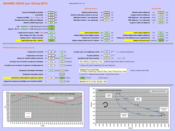
Click on the image above for a spreadsheet for a rhomboidal crankshaft beta engine
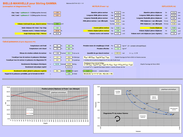
Click on the image above to access the spreadsheet of a connecting rod-crank Gamma engine
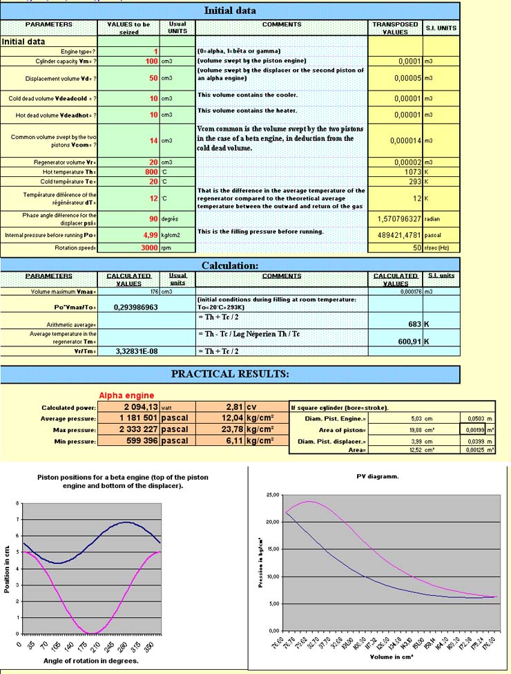
The worksheet made by
Jean-Pierre Van Dormael is remarkable, very well done and very practical.
It is possible for people to download it easily by clicking "Download worksheet".
Here a picture of this page of calculation:
This site was created and is maintained by Pierre Gras.
Thank you with all the people who contributed their shares: articles, photographs, videos, worksheets.
The author is opened with any suggestion allowing to improve this site for happiness of everybody. Finally, a big
thank you to Robert Stirling !
"stirlinengine.fr" site by Pierre Gras is licensed under a
Creative Commons License
 .
.
This site meets XHTML and CSS standards. To get the best, use a browser such as Firefox, Chrome, Safari, Opera... they also adhere to these standards.
